{:en}Design a flame detector through a raspberry pi board and flame sensor{:}{:ja}ラズパイで火炎検知センサーを作動する{:}{:zh}Design a flame detector through a raspberry pi board and flame sensor{:}
{:en}
Overview
This project introduces how to design a flame detector through a raspberry pi board and flame sensor.
The component parts
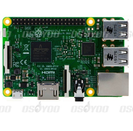 |
Pi3 x1
|
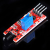 |
flame sensor x1 |
 |
Analog to digital convertor(ADC) x1 |
 |
Breadboard x1 |
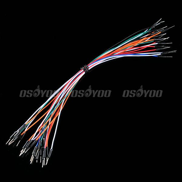 |
Jumper Wire |
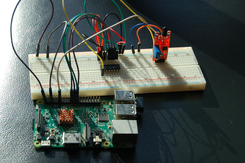
Hardware
Within the range of wave length 760-1100 nm,the flame sensor can both output the digital and analog signal. When the flame is detected by sensor,the digital signal would output the high level signal. The output voltage by analog signal is determined by the size of the flame. The bigger the flame size is, the high the voltage output. The sensitivity of the flame sensor can be adjusted by the adjustable potentiometer.
When the distance between lighter and flame sensor is 80cm, the flame can be detected by sensor. The larger the flame is, the farther the detected distance can be. The flame sensor is sensitive to the flame radiation spectrum if the detected angle is 60 degree.
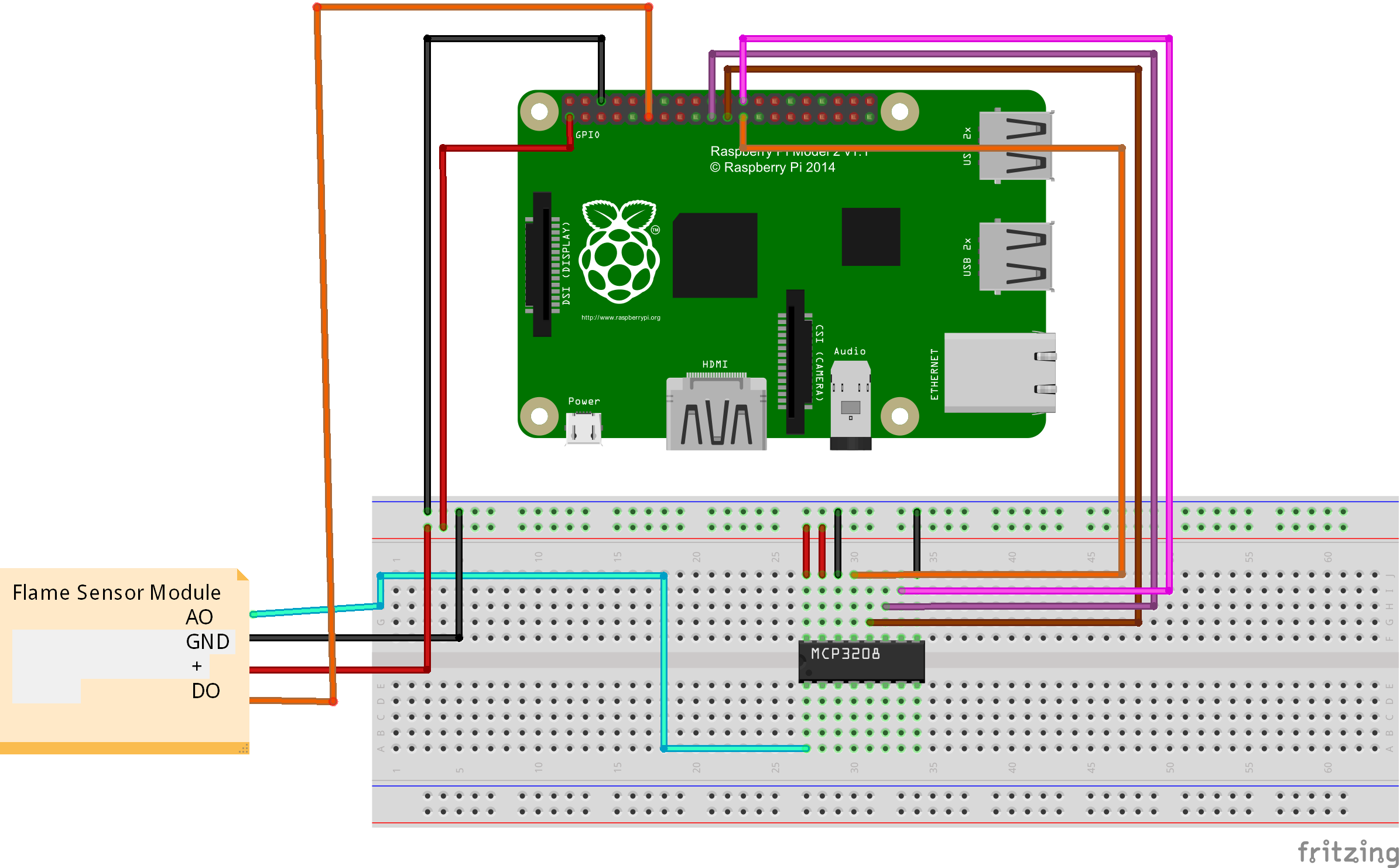
Pay more attention to the anode and cathode, otherwise it would burnout your raspberry pi board and flame sensor. You can connect the GND of flame sensor to OV, VCC to 3.3V. You could visit the article for your referenc if you want to learn more about the raspberry pi IO port. : How to read Raspberry Pi i/o pin diagram (GPIO pin graph)
Software
You could choose to connect the raspberry pi to monitor, or login in pi via SSH.
1)Compiling the code
enter the following command to create a new file named motionsensor-test.py and save this file at direction: /home/pi, and then press enter
Add new file named flame.py through nano editor (the name is arbitrary)
sudo nano flame.py
Write the sample code in new file, the code can be obtained by executing shell commands.
sudo wget --no-check-certificate http://osoyoo.com/driver/flame.py
2)Execute python program
sudo python ./flame.py
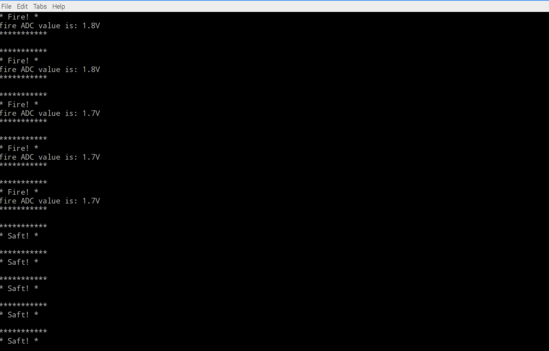
3)Test
When the programme start, you can open the lighter in front of flame sensor. The green light of flame sensor turns on and the prompt message would show on the monitor. The green lighter is not on if there is no flame. If the green light keep on without flame,you need to correct it via the adjustable potentiometer. The correct information is as follows:
{:}{:ja}
概要
本プロジェクトでは火炎検知センサーとラズパイ3ボードを使って、火炎検知装備を作ります。火炎検知センサーは火炎と波長760nm~1100nmの光が敏感します。アナログ信号とデジタル信号2重輸出できます、火炎が検出したら、デジタルOUTPUT(DO)から高電位信号を輸出して、アナログOUTPUT(AO)から電圧値を輸出します。火炎のサイズが大きくなると輸出したの電圧値も大きくなります。モジュールに可変抵抗がありますので、センサーの感度が調整しできます。
必要なパーツ
|
|
Pi3ボード x1
|
|
|
火炎検知センサーx1 |
|
|
MCP3008 A/Dコンバータx1 |
|
|
ブレッドボードx1 |
|
|
ジャンプワイヤー(オス~オス)x若干 |
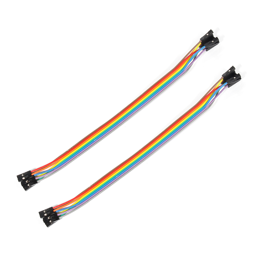 |
ジャンプワイヤー(オス~メス)x若干 |
ハードウェア
火炎検知センサーは火火炎と波長760nm~1100nmの光が検出しできます。点火しているライターを使用の場合、80CMの範囲内は検出しできます。検出の角度は60度となります。火炎のサイズが大きくなると、検出できる距離も拡大できます。モジュールに可変抵抗がありますので、センサーの感度が調整しできます。工作電圧は3.3V~5Vですので、本文では3.3Vでセンサーに給電します。
配線図
線路が違うとボード、センサーに損害の恐れが御座いますので、正極と負極を十分ご注意して下さい。Raspberry PiのGPIOピンの概要はこちら~
ソフトウエア
下記の操作は、ラズパイとスクリーンを接続しても、SSHを通じでラズパイと接続しても、操作できます。
1)プログラム
nanoエディタを使用して、下記のコマンドを作動して、/home/piにflame.pyと言うファイルを新規作成します。
sudo nano flame.py
ファイルにをコードをコーピーして、キーボードのCtrlとXボーダーを押して、Yを入力して、ファイルを保存します。
或いは、下記のコマンドを作動して、弊社編集済みのflame.pyを直接にダウンロードできます。
sudo wget --no-check-certificate http://osoyoo.com/driver/flame.py
2)下記のコマンドを作動して、pythonプログラムを作動する
sudo python ./flame.py
3)結果
点火したのライターがモジュールに近づいてくると、火炎が検出したら、モジュールでの指示ランプが点灯し、ターミナルにFire!と表示します。火炎が検出しない時、指示ランプ消灯して、ターミナルにSafe!と表示します。もし、点火したのライターがモジュールに近づいてくるても何も変化しないの場合、モジュールでの可変抵抗を調整して、確認して下さい。
{:}{:zh}Overview
本文介绍在树莓派如何使用火焰传感器设计火焰探测器。火焰传感器对波长在 760 纳米~1100 纳米范围内的光源,模块具有数字和模拟信号双路输出,当检测到有火焰时候数字输出口输出高电平,模拟输出口输出电压与火焰大小有关,火焰 越大电压越高。模块的灵敏度可通过可调电位器调节。
Experimental Parts
为了完成设计需要用到一下器件
|
|
Pi3 x1
|
|
|
火焰传感器模块 x1 |
|
|
模数转换器 x1 |
|
|
面包板 x1 |
|
|
公对公跳线 x若干 |
|
|
公对母跳线 x若干 |
Hardware
火焰传感器模块 可以检测火焰或者波长在 760 纳米~1100 纳米范围内的光源, 打火机测试火焰距离为 80cm,对火焰越大,测试距离越远 , 探测角度 60 度左右,对火焰光谱特别灵敏 。其灵敏度可以通过可调继电器调节,工作电压为3.3V-5V之间,本文用3.3V给火焰模块供电。与树莓派具体连接参考下图。
在接线的时候请认清模块正负极,不要接反了,否则会烧坏你的Pi和模块。模块的上的GND接Pi上的0V;模块上的VCC接3.3V。对于如何识别Pi的IO口请参考这篇文章: How to read Raspberry Pi i/o pin diagram (GPIO pin graph)
Software
可以把pi直接接到显示器上,也可以通过SSH方式远程登录Pi。
1)编写代码
在/home/pi路径下用nano新建一个flame.py(名字随意,你喜欢就好!)
sudo nano flame.py
并往新建的文件中写入示例代码,代码可以通过执行下面的shell命令得到
sudo wget --no-check-certificate http://osoyoo.com/driver/flame.py
2)执行python程序
sudo python ./flame.py
3)测试
程序运行起来后,用打火机对着模块打火,如果模块检测到火光,模块上的绿色LED指示灯会亮起来,同时屏幕上会打印出提示信息;如果没有打火机对着模块打火,绿色指示灯不亮,或者没有对着模打火绿色指示灯就已经亮起,可以通过调节可调电位器进行校正。正常情况下会输出如下信息。
{:}
amber administrator
About the Author