{:en}Design a voltmeter with the raspberry pi board and voltage sensor{:}{:ja}ラズパイ3、電圧検出センサーとMCP3008 A/Dコンバータを使って、電圧計を制作する{:}{:zh}用树莓派设计一个电压表{:}
{:en}
Overview
This project introduces how to design a voltmeter through the raspberry pi board and voltage sensor , and get the detected data on terminal.
The Component Parts
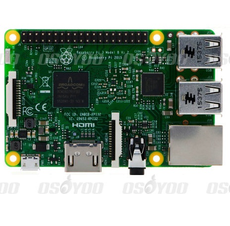 |
Raspberry Pi 3
|
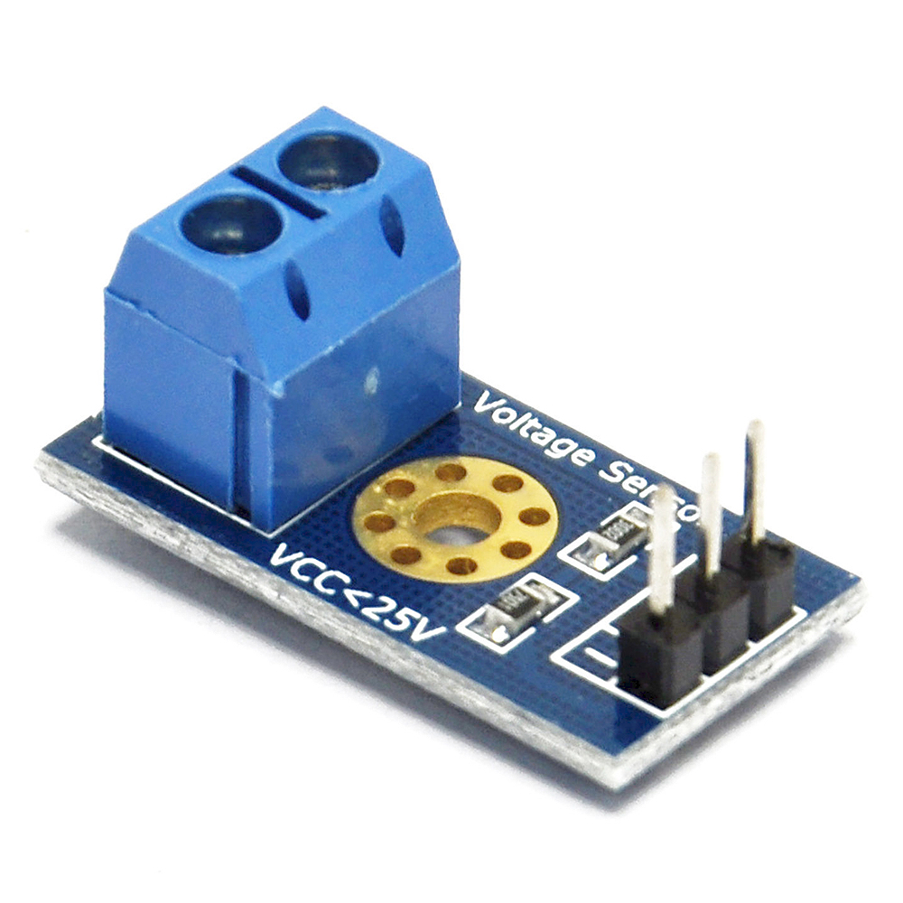 |
voltage sensor x1 |
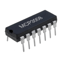 |
Analog to Digital Converter (ADC) x1 |
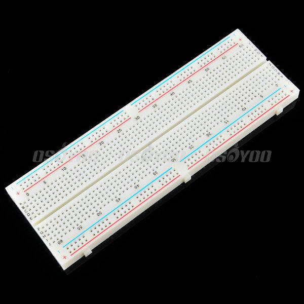 |
Breadboard x1 |
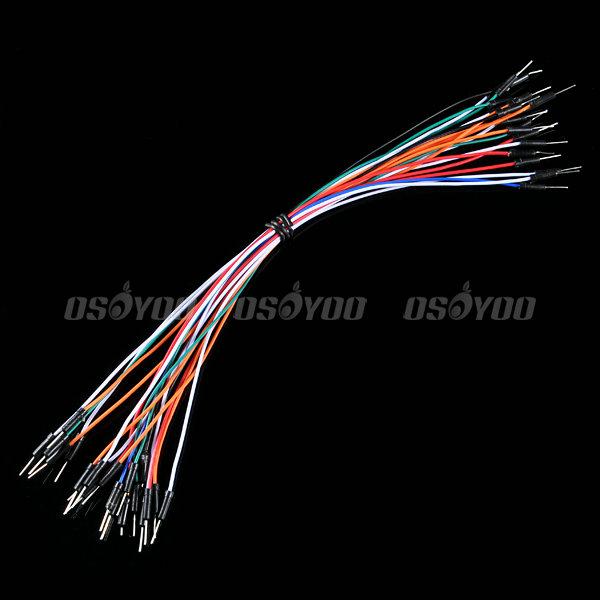 |
Jumper wire(male to male)
some |
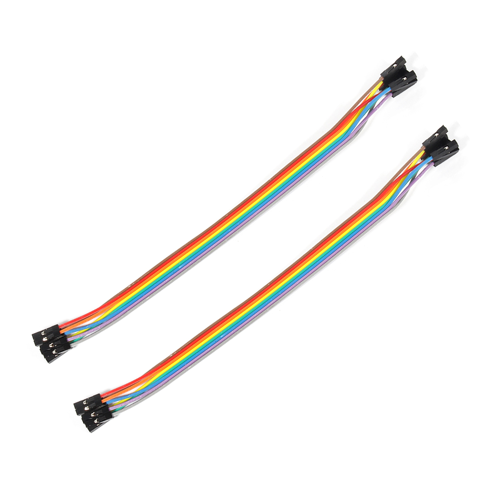 |
Jumper wire(female to female) some |
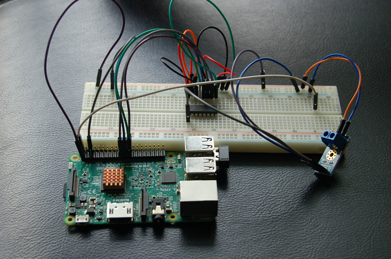
Hardware
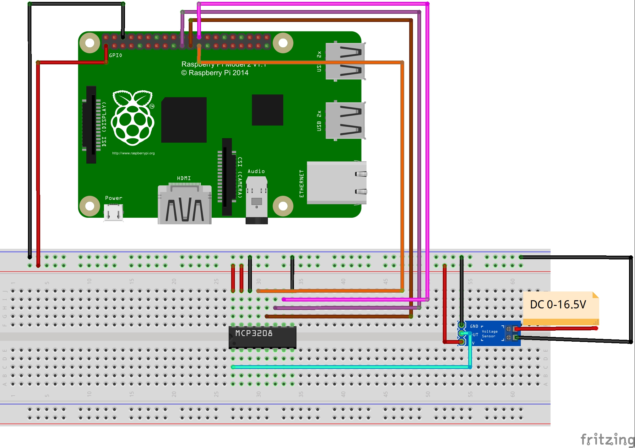
According to resistance divider, the voltage sensor can decreased the voltage to one fifth of the primary voltage. As the working voltage of raspberry pi is 3.3V, you had better input the voltage less than 16.5V (3.3 x 5 = 16.5V).
The output interface of voltage sensor should connect “+” to 3.3V,”-” to GND,”S” to the AD output of ADC. At the other end of voltage sensor, the anode to VCC and the cathode to GND.
As only the digital signal can be processed by raspberry pi, we need to add a analog to digital converter (ADC) to process the analog signal from voltage module. MCP3008 as ADC chip is very common and recommended highly.
Software
You could choose to connect the raspberry pi to monitor, or login in pi via SSH.
1)Write the code
1)enter the following command to create a new file named voltage.py and save this file at direction: /home/pi, and then press enter
sudo nano voltage.py
Enter the sample code in new file, the code can be got by executing shell commands.
sudo wget --no-check-certificate http://osoyoo.com/driver/voltage.py
2)Run python program
sudo python ./voltage.py
3) Test
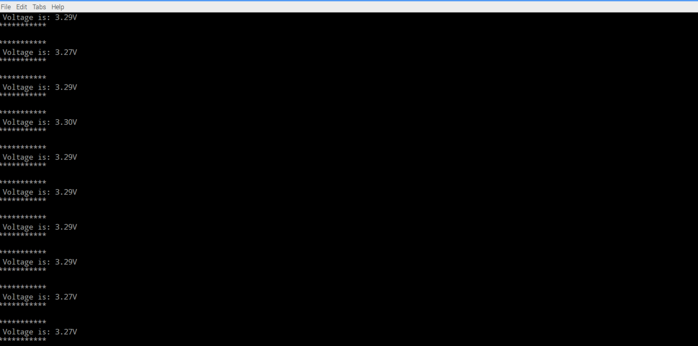
Connect the DC port to power supply less 16.5V, the monitor would show the voltage value. For example,you will get the value of 3.29V with the a little allowable error when it connect to 3.3v power supply.
{:}{:ja}
概要
本文では、ラズパイ3、電圧検出センサーとMCP3008 A/Dコンバータを使って、電圧計を制作して、電圧値をターミナルにプリントします。
必要なパーツ
|
|
Pi3ボード x1
|
|
|
電圧検出センサー x1 |
|
|
MCP3008 A/Dコンバータ x1 |
|
|
ブレッドボード x1 |
|
|
ジャンプワイヤー(オス~オス)x若干 |
|
|
ジャンプワイヤー(オス~メス)x若干 |
ハードウェア
このモジュールは抵抗分圧の原理に基づいて、デザインしました。輸入したの電圧値を5倍に下げて、輸出しできます。ラズパイGPIOの工作電圧は普段3.3Vのため、電圧検知モジュールへの輸入電圧はできるだけ、16.5V(3.3Vx5倍)以下にして下さい。出力インタフェース:”+”は3.3vに接続し、”-“は GNDに接続し、”s”はMCP3008 A/DコンバータのAD入力PINに接続します。
DC入力インタフェース:正極とVCC、負極とGND、下記の画像をご参照:
ラズパイはデジタル信号しか処理しできませんので、今回は電圧検知センサーからの電圧信号(アナログ信号)を処理するため、A/Dコンバータも必要です。本プロジェクトではMCP3008と言う、よく利用されるA/Dコンバータを使用します。
ソフトウエア
下記の操作は、ラズパイとスクリーンを接続しても、SSHを通じでラズパイと接続しても、操作できます。
1)プログラム
nanoエディタを使用して、下記のコマンドを作動して、/home/piに一个voltage.pyと言うファイルを新規作成します。
sudo nano voltage.py
ファイルにコードをコーピーして、キーボードの CtrlとXボーダーを押して、Yを入力して、ファイルを保存します。
或いは、下記のコマンドを作動して、弊社編集済みのvoltage.pyを直接にダウンロードできます。
sudo wget --no-check-certificate http://osoyoo.com/driver/voltage.py
2)下記のコマンドを作動して、pythonプログラムを作動する
sudo python ./voltage.py
3)結果
電圧検出センサーのDC入力端子と16.5V以下の電源アダプターを接続したら、検測したの電圧値がターミナルに表示します。例えば、電圧検出センサーのDC入力端子と3.3V電源アダプターを接続の場合、ターミナルに3.29Vぐらいの数値を表示します。A/Dコンバータで転換したの信号のため、少し誤差があるはずです。
{:}{:zh}Overview
本文中将介绍如何用树莓派和电压传感器设计电压表,把测量到的读数实时打印在终端上。
Parts
本项目将用到如下器件
|
|
Pi3 x1
|
|
|
电压传感器模块 x1 |
|
|
模数转换器 x1 |
|
|
面包板 x1 |
|
|
公对公跳线 x若干 |
|
|
公对母跳线 x若干 |
Hardware
电压传感器模块基于电阻分压原理所设计,能使端子接口输入的电压缩小5倍,由于树莓派GPIO工作电压一般是3.3V,所以模块输入电压最好低于3.3Vx5=16.5V),模块输出接口:”+”接3.3V, “-“接GND,”s”接ADC的AD输入端;DC输入接口:端子正极接VCC,负极接GND。如图
Raspberry Pi只能处理数字信号,需要处理的是电压传感器模块输出的电压信号,由于电压信号是模拟信号,所以需要使用ADC,本项目使用MCP3008作为ADC芯片,这是一片很常用的ADC芯片。
Software
可以把pi直接接到显示器上,也可以通过SSH方式远程登录Pi。
1)编写代码
在/home/pi路径下用nano新建一个voltage.py(名字随意,你喜欢就好!)
sudo nano voltage.py
并往新建的文件中写入示例代码,代码可以通过执行下面的shell命令得到
sudo wget --no-check-certificate http://osoyoo.com/driver/voltage.py
2)执行python程序
sudo python ./voltage.py
3)测试
将模块的DC输入端子接到电压小于16.5V的电源上,屏幕会输出检测到的电压。例如将DC输出口接到3.3V电源上,屏幕会输出3.29V,会有一点的误差,毕竟是通过ADC后得到的电压值。
{:}
amber administrator
You must be logged in to post a comment
About the Author