4 Inches TFT Touch Screen for Arduino Mega2560
![]()
| Buy from US | Buy from UK | Buy from DE | Buy from IT | Buy from FR | Buy from ES | Buy from JP |
Content
1 Product Picture
2 Product Description
3 Product Parameters
4 Interface Definition
5 Connect to Arduino
6 How to use on Arduino
7 Program Download

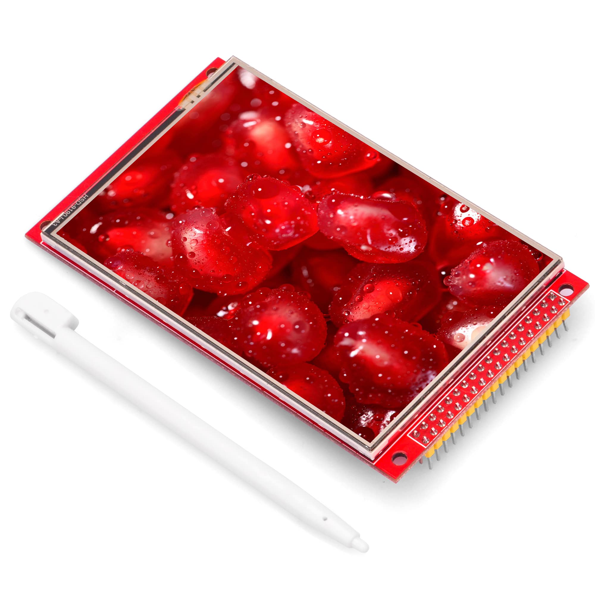
Product Picture
Product Description
-
- Support Arduino Mega2560 direct plug-in use
- 3.95-inch color screen, support 16BIT RGB 65K color display, display rich colors
- 320×480 resolution for clear display
- Supports 8-bit and 16-bit parallel bus transmission with fast transfer speed
- On-board 5V/3.3V level shifting IC, compatible with 5V/3.3V operating voltage
- Support touch function
- Provides an Arduino library with a rich sample program
- Available on C51 and STM32 platforms with a rich sample program
- Easy to expand the experiment with SD card slot
- Military-grade process standards, long-term stable work
- Provide underlying driver technical support
Product Parameters
| Name | Parameter |
| Display Color | RGB 65K color |
| SKU | MAR3953 |
| Screen Size | 3.95(inch) |
| Type | TFT |
| Driver IC | ST7796S |
| Resolution | 480*320 (Pixel) |
| Module Interface | 8Bit or 16Bit parallel interface |
| Active Area | 83.52×55.68(mm) |
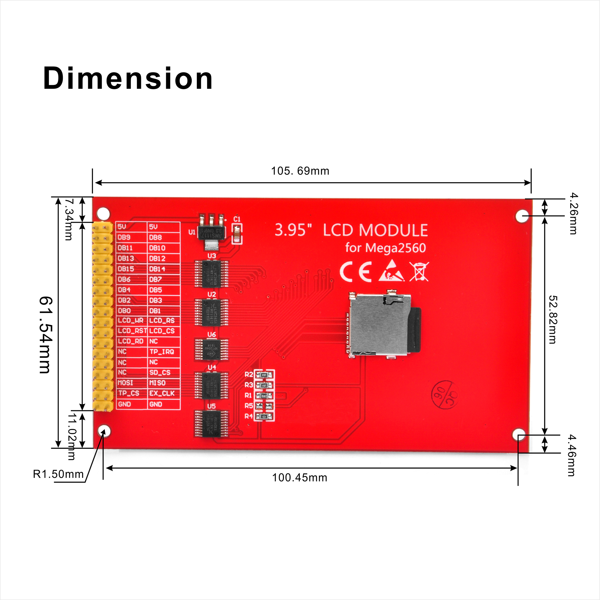
| Module PCB Size | 61.54×105.69 (mm) |
| back light | 6 chip HighLight white LEDs |
| Operating Temperature | -20℃~60℃ |
| Storage Temperature | -30℃~70℃ |
| Operating Voltage | 5V/3.3V |
| Power Consumption | TBD |
| Product Weight(Package containing) | 68 (g) |
Interface Definition
The blue box in the above figure is the 8-bit/16-bit data bus mode switch, which is described as follows:
- Solder R5 with 0Ω resistor or short circuit directly, and disconnect R4: select 16-bit data bus mode (default), use DB0~DB15 data pin
- Solder R4 with 0Ω resistor or short circuit directly, and disconnect R5: select 8-bit data bus mode, use DB0~DB7 data pin
| Number | Module Pin | Pin Description | Number | Module Pin | Pin Description |
|---|---|---|---|---|---|
| 1 | 5V | Positive power supply | 2 | 5V | Positive power supply |
| 3 | DB8 | 8th bit of data bus(No need to use when using 8-bit mode) | 4 | DB9 | 9th bit of data bus(No need to use when using 8-bit mode) |
| 5 | DB10 | 10th bit of data bus(No need to use when using 8-bit mode) | 6 | DB11 | 11th bit of data bus(No need to use when using 8-bit mode) |
| 7 | DB12 | 12th bit of data bus(No need to use when using 8-bit mode) | 8 | DB13 | 13th bit of data bus(No need to use when using 8-bit mode) |
| 9 | DB14 | 14th bit of data bus(No need to use when using 8-bit mode) | 10 | DB15 | 15th bit of data bus(No need to use when using 8-bit mode) |
| 11 | DB7 | 7th bit of data bus | 12 | DB6 | 6th bit of data bus |
| 13 | DB5 | 5th bit of data bus | 14 | DB4 | 4th bit of data bus |
| 15 | DB3 | third bit of data bus | 16 | DB2 | 2nd bit of data bus |
| 17 | DB1 | 1st bit of data bus | 18 | DB0 | 0 bit of data bus |
| 19 | LCD_RS | LCD register / data selection signalLow level: register, high level: command | 20 | LCD_WR | LCD write control signal |
| 21 | LCD_CS | LCD screen select control signal, low level enable | 22 | LCD_RST | LCD reset control signal, low reset |
| 23 | NC | Undefined, reserved | 24 | LCD_RD | LCD read control signal |
| 25 | TP_IRQ | Touch screen interrupt control signal, low level when touch is detected | 26 | NC | Undefined, reserved |
| 27 | NC | Undefined, reserved | 28 | NC | Undefined, reserved |
| 29 | SD_CS | SD card select control signal, low level enable | 30 | NC | Undefined, reserved |
| 31 | MISO | SPI bus input signal | 32 | MOSI | Touch screen chip select control signal, low level enable |
| 33 | EX_CLK | SPI bus clock signal | 34 | TP_CS | SD card select control signal, low level enable |
| 35 | GND | Power ground | 36 | GND | Power ground |
********************************************************************************
Connect to Arduino Mega2560

How to use on Arduino
- Step 1: Download the test program
- Download the Arduino test program: http://osoyoo.com/driver/screen/3.95inch-screen-for-arduino-mega2560/test.zip
- For a description of the relevant test procedures, please refer to the test program documentation in the package
- Step 2: Connect the Arduino development board
- Plug the module directly into the Arduino development board
- After the module is plugged in, power on the Arduino board
- Step 3: Copy the dependent library
- Make sure the Arduino IDE is installed on your computer (if it is not installed: Arduino IDE download URL)
- After installing the Arduino IDE, you need to copy the dependent library to the Arduino project directory as follows:
-
- (1) Decompress the downloaded test package


- (2) Copy the dependent libraries in the Install libraries directory in the package (shown below) to the libraries folder of the Arduino project directory (the default Arduino project directory is C:\Users\Administrator\ Documents\Arduino\libraries).

- Step 4: Compile and download the program to the development board
- Open the sample in the Example directory of the package to test, compile and download( Don’t know how to compile and download?)
- Step 5: Observe the running of the program
-
-
- After the program is downloaded, run it directly and observe the running status. If it can be displayed normally, the program runs successfully, as shown in the following figure (take the colligate_test test program as an example):


- This set of test procedures contains the following test items:
- Example_01_Simple_test is a simple swipe test that does not depend on the library, can be used to detect the LCD hardware;
B.Example_02_clear_screen is a simple solid color brush test;
- Example_03_colligate_test is a comprehensive test, including graphics, lines, text display;
- Example_04_display_graph is a graphical display test, including graphics drawing and filling test;
- Example_05_display_scroll for character and graphic scroll display test;
- Example_06_display_string is a character display test;
- Example_07_show_bmp_picture is a picture display test, read the bmp picture in the SD card and display it;
- ExampIe_08_switch_test is the switch display and touch test;
- ExampIe_09_dispIay_phonecaII is a telephone dialing interface display and touch test;
- ExampIe_10_touch_pen is a touch pen test;
- SDCard Exten Example for Arduino platform SD card function test, including writing and reading;
-
amber administrator
You must be logged in to post a comment
About the Author