{:en}Serial to Parallel Shifting-Out with a 74HC595{:}{:ja}74HC595 シフトレジスターを使って、直列入力並列出力プロジェクト{:}
{:en}

At sometime or another you may run out of pins on your Arduino board and need to extend it with shift registers. This example is based on the 74HC595. The datasheet refers to the 74HC595 as an “8-bit serial-in, serial or parallel-out shift register with output latches; 3-state.” In other words, you can use it to control 8 outputs at a time while only taking up a few pins on your microcontroller.
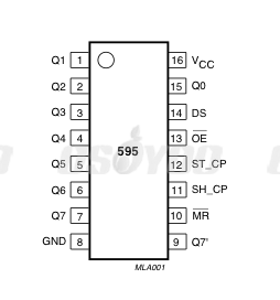
The 74HC595 IC chip has eight parallel output data pin (pin 15 and pin 1 to 7),one serial input pin(Pin 14) and two control pins-( pin 11(clock pin) and pin 12(latch pin)).
Pin diagram is as following:

In this project We will use 74HC595 to light up 8 LED one by one.
Step 1 – connect 74HC595 with Arduino
DS (pin 14) to Ardunio DigitalPin 11 (blue wire)
SH_CP (pin 11) to to Ardunio DigitalPin 12 (yellow wire)
ST_CP (pin 12) to Ardunio DigitalPin 8 (green wire)

Step 2 – add 8 LED lights

Step 3 – Download HC595.ino sketch file and load it into Arduino. The eight LEDs will loop lighting one by one.
Project Demo Video:
{:}{:ja}
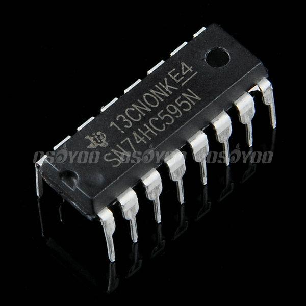
Arduinoボードのpinが足りない場合がときどきありますね、そのときシフトレジスターを使って、拡張pinの作りは必要になります。このプロジェクトは74HC595シフトレジスターを使用します。
74HC595シフトレジスターは、8ビット直列入力、直列出力、並列出力、出力ラッチ、3ステートバッファ搭載のシフトレジスターです。 つまり、このシフトレジスターを使って、Arduinoなどのマイクロコントローラと繋ぎ、同時に8台のデバイスが制御できます。
74HC595 IC は8個の並列出力pin(pin 15とpin 1~7)、1個の直列入力pin(Pin 14) 、 2個の制御pin「 pin 11(時計pin) and pin 12(ラッチ pin)」が搭載します。
画像をご覧ください~(画像をクリックして拡大イメージを表示)
74HC595を使って、8個のLEDを点灯するのプロジェクトです。
Step 1 – 74HC595と Arduinoボードを接続してくださいませ。
DS (pin 14) とArdunio のデジタルPin 11 (青ワイヤー)を接続する
SH_CP (pin 11)と ArdunioのデジタルPin 12 (黄色いワイヤー)を接続する
ST_CP (pin 12) と ArdunioのデジタルPin 8 (緑ワイヤー)を接続する
Step 2 – LEDを接続してくださいませ。
Step 3 – HC595.inoというファイルをダウンロードして、 Arduinoにロードしてくださいませ。ロード完了したら、LEDは次々に点灯します。
プロジェクトの動画をご覧ください~
{:}
admin administrator
You must be logged in to post a comment
About the Author