{:en}Design a light sensor switch through raspberry pi and photoresistor sensor{:}{:zh}长夜漫漫,不再黑暗{:}
{:en}
Overview
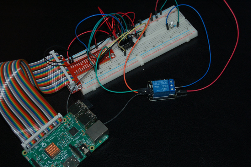
Photoresistor is a special resistor which takes advantage of Photoconductive effect, and its resistor value can change according to Lightness. The resistor value is low when it detect strong lightness, else, the value will be high when it detect weak lightness. A lot of products utilize this feature of photoresistor, such as camera, lawn lamp, sound light switch, streetlight recloser. In this project, we use a photoresistor, relay module with raspberry pi to design a light recloser. When the light becomes dark, the relay module closes and LED turns on. Otherwise,when the light becomes brighten, the relay module will break off and LED turn off.
Experimental photo
Parts
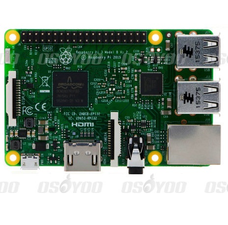 |
Pi3 x1
|
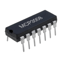 |
MCP2008 x1
(MCP3204 x1)
|
 |
Photoresistor x1
|
 |
LED x1
|
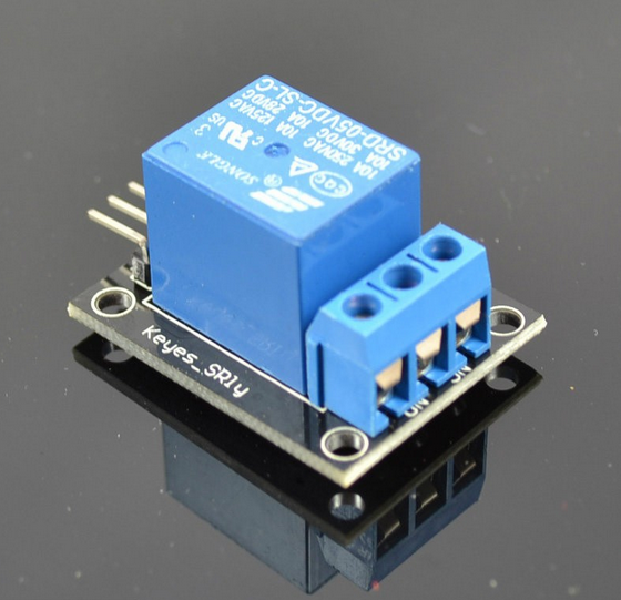 |
Relay module x1
|
 |
10KΩ resistor x1
1KΩ resistor x1
|
 |
some jumper wires
|
 |
Breadboard x1
|
Hardware
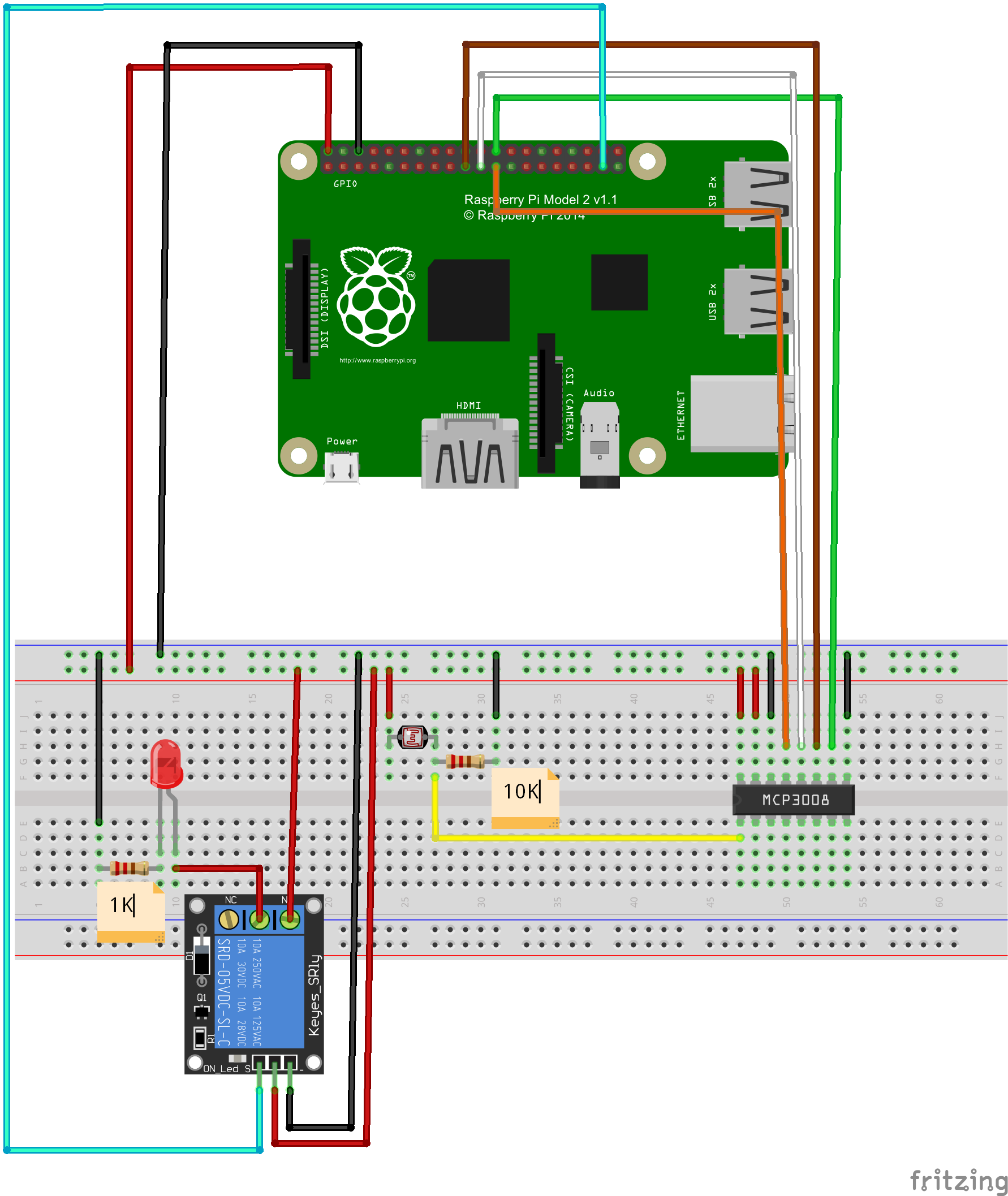
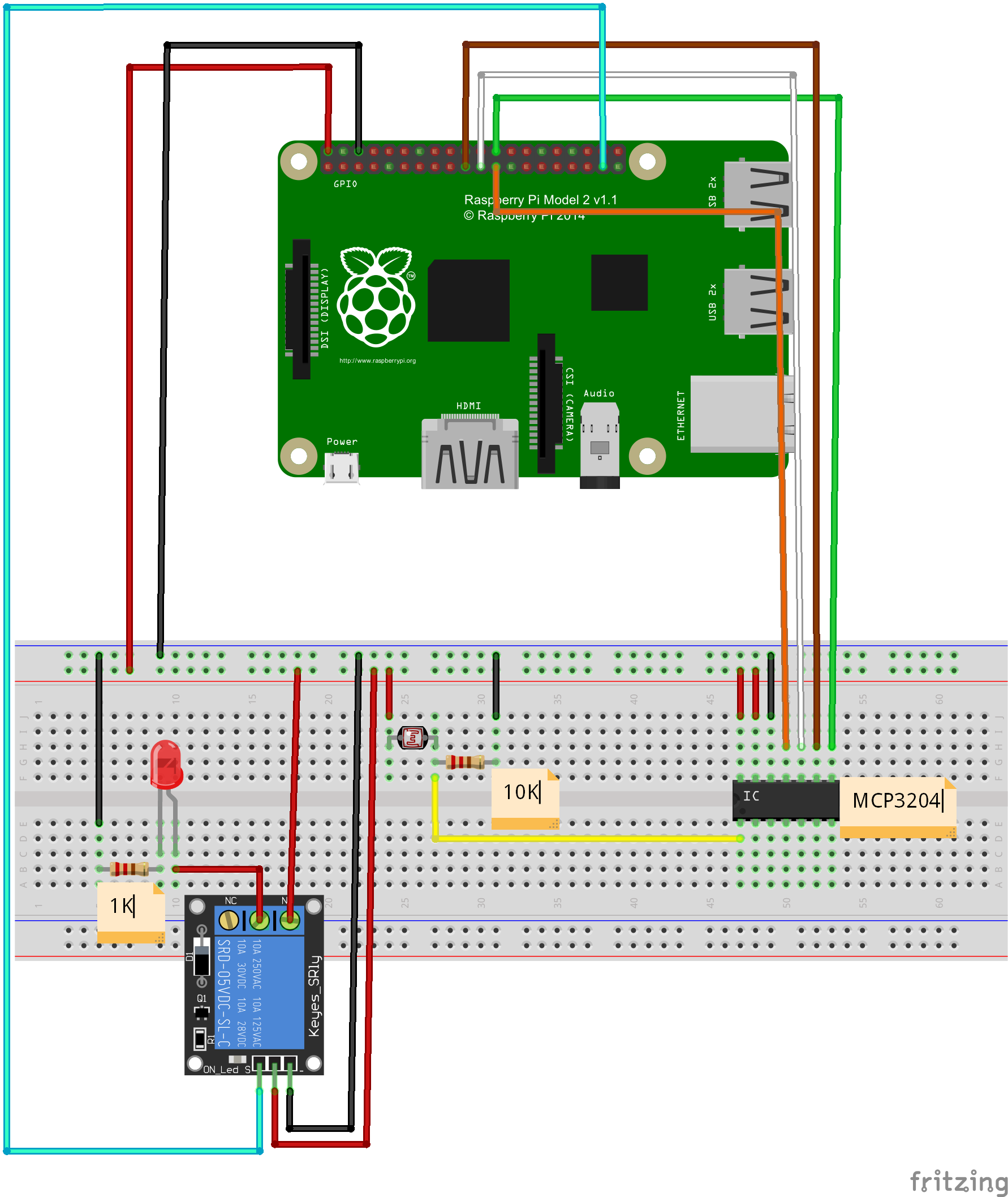
Raspberry Pi can work as a micro PC. The raspberry pi can handle digital signal, but when it handle analog signal ,such as thermistor, potentiometer etc, it need a analog to digital converter. In this project, we use MCP3008(or MCP3204)to convert voltage value signal from light sensor to digital signal. Raspberry pi control relay module break-make and LED on-off according to the digital value after converting. MCP3008 is a 10Bit 8-Kanal SPI Interface IC CHIP. MCP3204 is a 12Bit 4-Kanal SPI Interface IC CHIP. 1-Channel Relay Module works when get a high level. In another word, raspberry pi launch high level to relay module, and the relay module conduction and the indicator light on relay module is on. when raspberry pi launch low level, the relay module break off and the indicator light is off.
Circuit Graph with MCP3008:
Circuit Graph with MCP3204:
Software
(1)Before Python programming, Install GPIO library and Python library file in raspberry pi:
open terminal, update the apt-get software installation package list (Note: Network must be connected), and then enter installation command to install the raspberry gpio-python package.
Follow the next commands to complete installation, after entering each commands in terminal, press “enter” to complete:
1)Update software list:
pi@raspberrypi ~ $ sudo apt-get update
2)install python
pi@raspberrypi ~ $ sudo apt-get install python-dev
3)install python-pip (python-pip is a manager for python software package)
pi@raspberrypi ~ $ sudo apt-get install python-pip
4)Install rpi.gpio with pip:
pi@raspberrypi ~ $ sudo pip install rpi.gpio
5) testing:
pi@raspberrypi ~ $
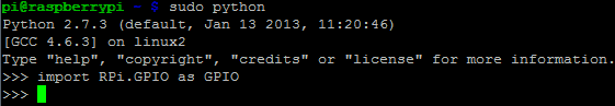
sudo python
After all steps, you will see the following photo. It means it is successful
to install GPIO library and Python library file. You can begin to program this
project via Python
(3)Programming
You can compile code not only through connecting monitor with your Pi, also
through SSH. You can choose two methods to compile the project code.
A. File editor to compile code:
1)create a new file “raspi-adc-photo.py” in any direction (such as
“/home/pi/”), and enter the following command
and then press enter:
pi@raspberrypi ~ $ sudo touch raspi-adc-photo.py
2)Open file raspi-adc-photo.py, and enter the
following command and then
press enter::
pi@raspberrypi ~ $ sudo nano raspi-adc-photo.py
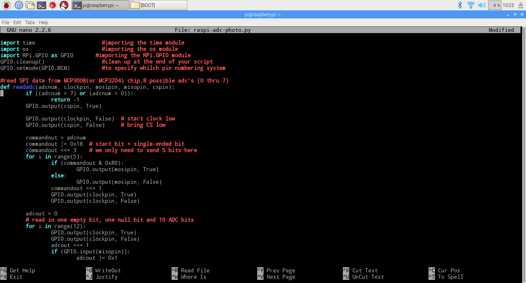
3)paste the following code in the file raspi-adc-photo.py
import time      #importing the time module
import os     #importing the os module
import RPi.GPIO as GPIO       #importing the RPi.GPIO module
GPIO.cleanup()      #clean up at the end of your script
GPIO.setmode(GPIO.BCM)    #to specify whilch pin numbering system

#read SPI data from MCP3008(or MCP3204) chip,8 possible adc's (0 thru 7)
def readadc(adcnum, clockpin, mosipin, misopin, cspin):
        if ((adcnum > 7) or (adcnum < 0)):
                return -1
        GPIO.output(cspin, True)

        GPIO.output(clockpin, False)  # start clock low
        GPIO.output(cspin, False)     # bring CS low

        commandout = adcnum
        commandout |= 0x18  # start bit + single-ended bit
        commandout <<= 3    # we only need to send 5 bits here
        for i in range(5):
                if (commandout & 0x80):
                        GPIO.output(mosipin, True)
                else:
                        GPIO.output(mosipin, False)
                commandout <<= 1
                GPIO.output(clockpin, True)
                GPIO.output(clockpin, False)

        adcout = 0
        # read in one empty bit, one null bit and 10 ADC bits
        for i in range(12):
                GPIO.output(clockpin, True)
                GPIO.output(clockpin, False)
                adcout <<= 1
                if (GPIO.input(misopin)):
                        adcout |= 0x1

        GPIO.output(cspin, True)

        adcout >>= 1       # first bit is 'null' so drop it
        return adcout

# change these as desired - they're the pins connected from the
# SPI port on the ADC to the Cobbler
SPICLK = 11
SPIMISO = 9
SPIMOSI = 10
SPICS = 8

# set up the SPI interface pins
GPIO.setup(SPIMOSI, GPIO.OUT)
GPIO.setup(SPIMISO, GPIO.IN)
GPIO.setup(SPICLK, GPIO.OUT)
GPIO.setup(SPICS, GPIO.OUT)

#relay port to the cobbler
Relay_pin = 26

#set up the relay port
GPIO.setup(Relay_pin,GPIO.OUT)

#disable the gpio warning information
GPIO.setwarnings(False)

# photoresistor connected to adc #0
photo_ch = 0;

#last_read = 0       # this keeps track of the last potentiometer value
#tolerance = 5       # to keep from being jittery we'll only change
                    # volume when the pot has moved more than 5 'counts'
print"______________________________________________________________________"
while True:
  photo_value = readadc(photo_ch, SPICLK, SPIMOSI, SPIMISO, SPICS)
  if(photo_value<=300):
    print "It`s dark,turn on the light"
    GPIO.output(Relay_pin,True)
  else:
    print "dawn,turn off the light"
    GPIO.output(Relay_pin,False)

  print "photo_value=", photo_value
  time.sleep(0.5)

#GPIO.cleanup()
4) after compile the project, press “Ctrl” + “X” to save the code, enter “Y”
to confirm saving, and press “enter” to exit the file editor
B. Command to compile code
Enter the command wget –no-check-certificate http://osoyoo.com/driver/raspi-adc-photo.py,
and press “enter” to complete compiling code.
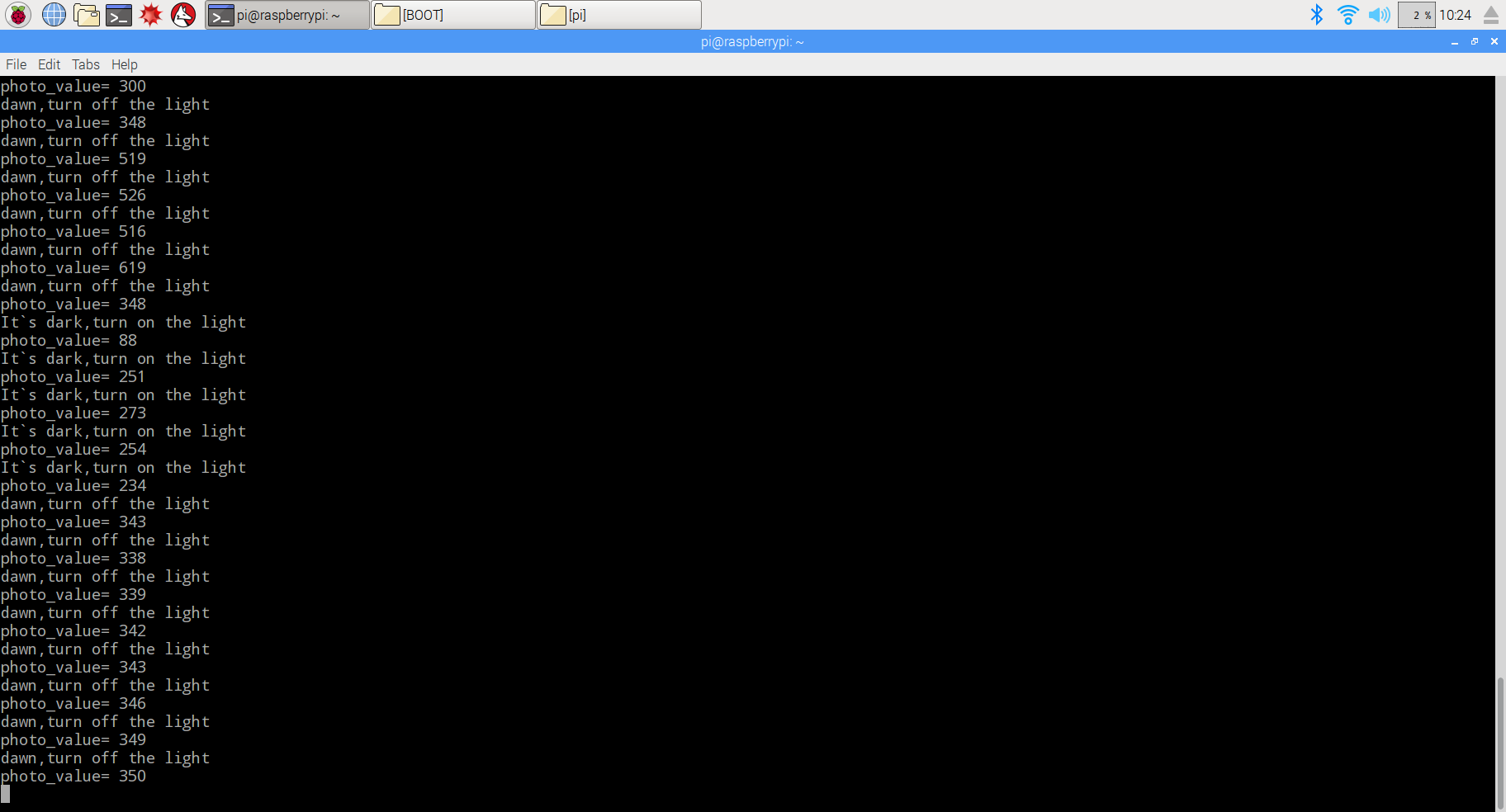
(3)Experiment Result:
Enter the following command
pi@raspberrypi ~ $ sudo python ./raspi-adc-photo.py
And press “enter” to run the project, and you will see the photo as following. When covering photoresistor, the relay module closes and LED turns on. Otherwise, when uncovering photoresistor, the relay module will break off and LED turn off.
 {:}{:zh}Overview
光敏电阻是是利用光电导效应的一种特殊的电阻,它的电阻和光线的强弱有直接关系,光强度增加,则电阻减小;光强度减小,则电阻增大。利用这一特性可以做很多东西,比如照相机、草坪灯、声光控开关、路灯自动开关等。本项目我们在树莓派上用光敏电阻、继电器等器件完成路灯自动开关制作。当光照比较暗的时候继电器闭合点亮LED灯;光照变亮的时候,继电器断开,LED熄灭。
Parts
|
|
光敏电阻 x1
|
|
|
Pi3 x1
|
|
|
LED x1
|
|
|
继电器 x1
|
 |
10K电阻 x1
|
|
|
1K电阻 x1
|
 |
跳线若干
|
 |
面包板 x1
|
|
|
MCP2008 x1
(MCP3204 x1)
|
Hardware
Raspberry Pi是一个出色的微型计算机,你可以使用它来控制数字输入和输出。但是当你想用它来处理模拟信号,例如像热敏电阻、电位器等模拟传感器输出时候,Raspberry Pi就有些力不从心了,就需要借助模数转换芯片将模拟信号转换成数字信号。本项目中利用MCP3008(or MCP3204)把光敏电阻输出的电压信号转换成数字信号,Pi根据转换后的数值大小控制继电器通断,从而控制灯亮灭。MCP3008是一款8通道10位精度的模数转换芯片;MCP3204是一款4通道12位精度的模数装换芯片。一路继电器模块是高电平有效,即控制器(Pi)给继电器一个高电平,继电器导通,继电器模块上的LED指示灯亮起;低电平断开,继电器模块上的LED指示灯灯熄灭。
MCP3008接线图:
MCP3204接线图:
Software
(1)在开始编写程序前需要对我们的树莓派Python库文件进行安装设置,此处要用到GPIO库,先安装GPIO库,打开终端,更新apt-get软件安装包列表(注意必须要在网络连接正常情况下),然后执行安装命令来安装raspberry-gpio-python包(如果已经安装请跳过此步),具体指令如下:
1)更新源
pi@raspberrypi ~ $ sudo apt-get update
2)安装python
pi@raspberrypi ~ $ sudo apt-get install python-dev
3)安装python-pip(python-pip是一个管理python软件包的工具)
pi@raspberrypi ~ $ sudo apt-get install python-pip
4)利用pip安装rpi.gpio
pi@raspberrypi ~ $ sudo pip install rpi.gpio
(2)测试是否安装成功

通过上述几个步骤,已经安装好了Python与树莓派外置硬件GPIO库文件,在接下来的程序里就可以直接调用代码了。
(3)编写代码
你可以将Pi接到一台显示器上编写代码,也可以通过SSH连接到你的Pi编写代码
1)在Pi中任一目录下(如/home/pi/)新建一个led.py文件
pi@raspberrypi ~ $ sudo touch raspi-adc-photo.py
2)打开raspi-adc-photo.py文件
pi@raspberrypi ~ $ sudo nano raspi-adc-photo.py
3)向raspi-adc-photo.py中写入如下代码
import time      #importing the time module
import os     #importing the os module
import RPi.GPIO as GPIO       #importing the RPi.GPIO module
GPIO.cleanup()      #clean up at the end of your script
GPIO.setmode(GPIO.BCM)    #to specify whilch pin numbering system

#read SPI data from MCP3008(or MCP3204) chip,8 possible adc's (0 thru 7)
def readadc(adcnum, clockpin, mosipin, misopin, cspin):
        if ((adcnum > 7) or (adcnum < 0)):
                return -1
        GPIO.output(cspin, True)

        GPIO.output(clockpin, False)  # start clock low
        GPIO.output(cspin, False)     # bring CS low

        commandout = adcnum
        commandout |= 0x18  # start bit + single-ended bit
        commandout <<= 3    # we only need to send 5 bits here
        for i in range(5):
                if (commandout & 0x80):
                        GPIO.output(mosipin, True)
                else:
                        GPIO.output(mosipin, False)
                commandout <<= 1
                GPIO.output(clockpin, True)
                GPIO.output(clockpin, False)

        adcout = 0
        # read in one empty bit, one null bit and 10 ADC bits
        for i in range(12):
                GPIO.output(clockpin, True)
                GPIO.output(clockpin, False)
                adcout <<= 1
                if (GPIO.input(misopin)):
                        adcout |= 0x1

        GPIO.output(cspin, True)

        adcout >>= 1       # first bit is 'null' so drop it
        return adcout

# change these as desired - they're the pins connected from the
# SPI port on the ADC to the Cobbler
SPICLK = 11
SPIMISO = 9
SPIMOSI = 10
SPICS = 8

# set up the SPI interface pins
GPIO.setup(SPIMOSI, GPIO.OUT)
GPIO.setup(SPIMISO, GPIO.IN)
GPIO.setup(SPICLK, GPIO.OUT)
GPIO.setup(SPICS, GPIO.OUT)

#relay port to the cobbler
Relay_pin = 26

#set up the relay port
GPIO.setup(Relay_pin,GPIO.OUT)

#disable the gpio warning information
GPIO.setwarnings(False)

# photoresistor connected to adc #0
photo_ch = 0;

#last_read = 0       # this keeps track of the last potentiometer value
#tolerance = 5       # to keep from being jittery we'll only change
                    # volume when the pot has moved more than 5 'counts'
print"______________________________________________________________________"
while True:
  photo_value = readadc(photo_ch, SPICLK, SPIMOSI, SPIMISO, SPICS)
  if(photo_value<=300):
    print "It`s dark,turn on the light"
    GPIO.output(Relay_pin,True)
  else:
    print "dawn,turn off the light"
    GPIO.output(Relay_pin,False)

  print "photo_value=", photo_value
  time.sleep(0.5)

#GPIO.cleanup()
也可以通过如下命令下载得到:
4)保存退出
编写完程序后,键盘输入”Ctrl X”,提示是否保存退出,键入Y然后回车就可以保存退出了
(5)运行程序,查看效果
pi@raspberrypi ~ $ sudo python ./raspi-adc-photo.py
用手遮住光敏电阻可以听到继电器闭合声,灯亮起;用光照着光敏电阻,也能听到继电器断开的声音,灯熄灭。{:}
amber administrator
You must be logged in to post a comment
About the Author