{:en}Design sound light switch throught raspberry pi and sound light sensor{:}{:zh}用树莓派实现声光控开关{:}
{:en}
Overview
This tutorial introduce how to design a sound and light switch with raspberry pi. The sound and light switch turns on and off via sound decibel and light value. When the light value is under the setting value in the code, meanwhile,
the sound is over the setting decibel, the switch will turn on. In this project, the raspberry pi receive the signal from sound sensor module and light sensor module, and then analyze the signal to control the switch, the switch means a
software switch (controlled by software). when the switch turn on, you will hear buzzer sound.
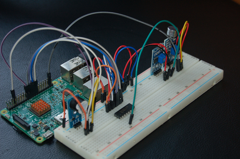
Experimental photo:
Experimental Parts
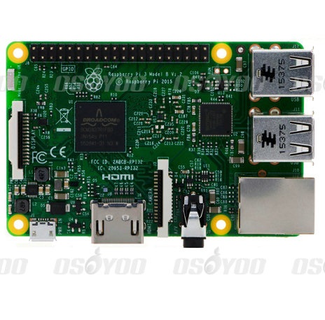 |
Raspberryp Pi 3
|
x1
|
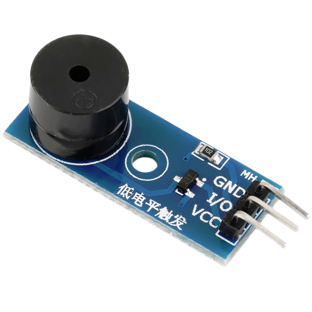 |
Buzzer module
|
x1
|
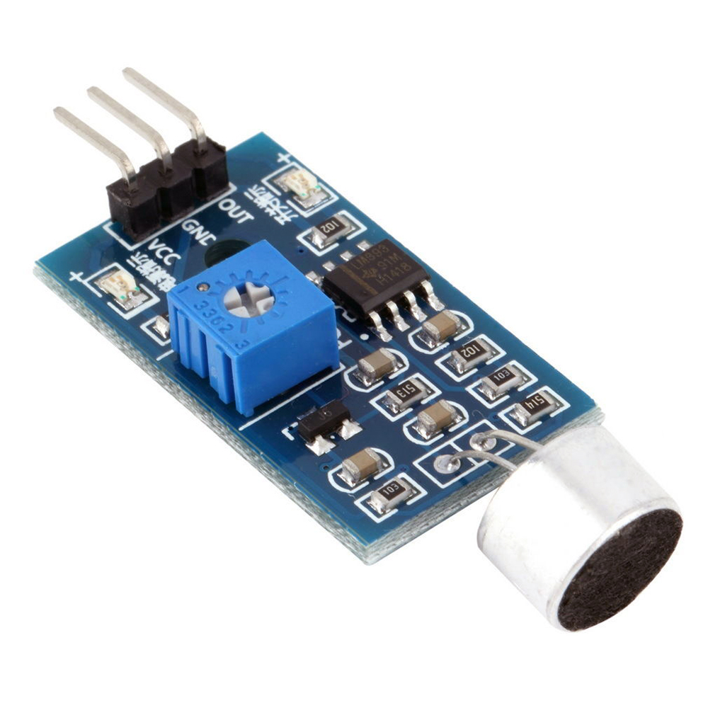 |
Sound sensor Module
|
x1
|
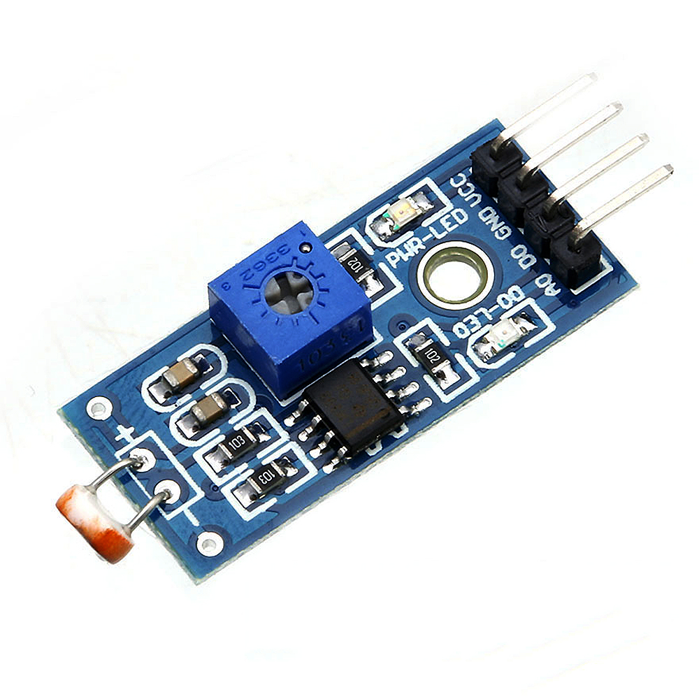 |
Light sensor module
|
x1
|
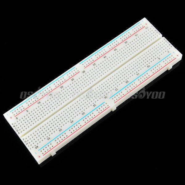 |
breadboard
|
x1
|
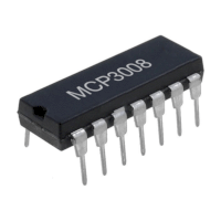 |
I/P Analog To Digital Converter
|
x1
|
 |
Male to Male Jumper wire
|
certain amount
|
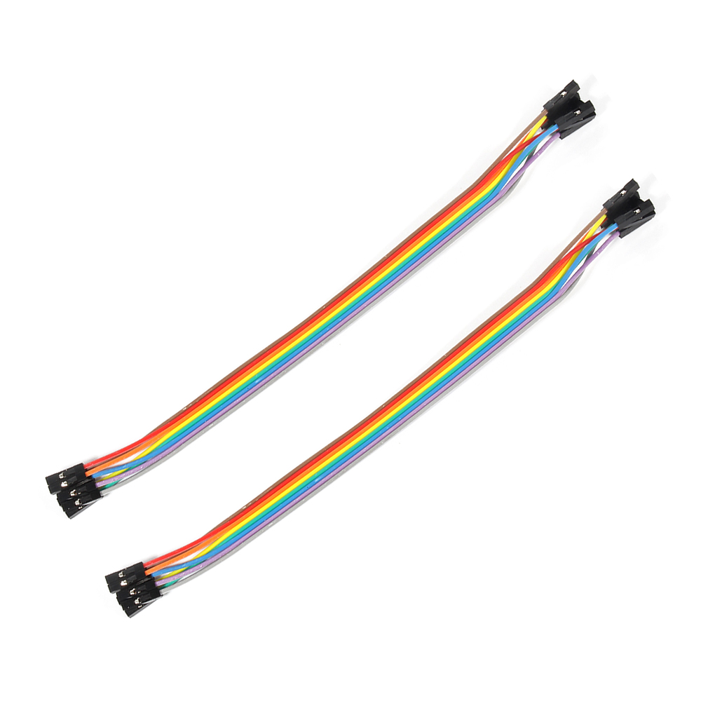 |
Female to Male Jumper wire
|
certain amount
|
Hardware
Raspberry Pi can work as a micro PC. the raspberry pi can handle digital signal, but when it handle Analog signal from such as thermistor, Potentiometer etc, it need a Analog To
Digital Converter. In this project, we use MCP3008 to convert voltage value signal from light sensor to digital signal. Raspberry pi control buzzer according to the digital value after converting. MCP3008 is a 10Bit
8-Kanal SPI Interface IC CHIP.
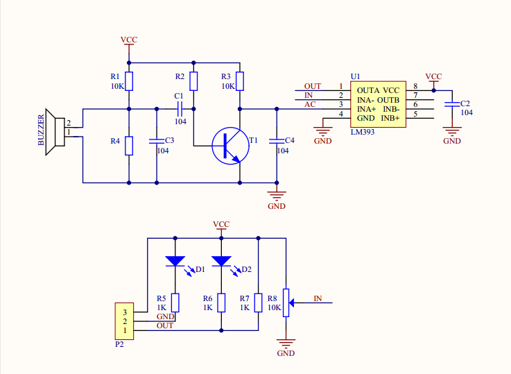
Sound sensor module can detect not only sound, but also the sound or special frequency. It can be adjusted via the blue Potentiometer. This sensor module can work under 3.3V and
5V, but the raspberry Pi GPIO output 3.3V generally, so the sensor connect with 3.3V GPIO. This module can output digital signal “0” and “1”. When the module detect the sound below value of the code, D0 pin of the module will output high
level. else, D0 will output low level.
Sound sensor module Schematic as follow:
Circuit Graph
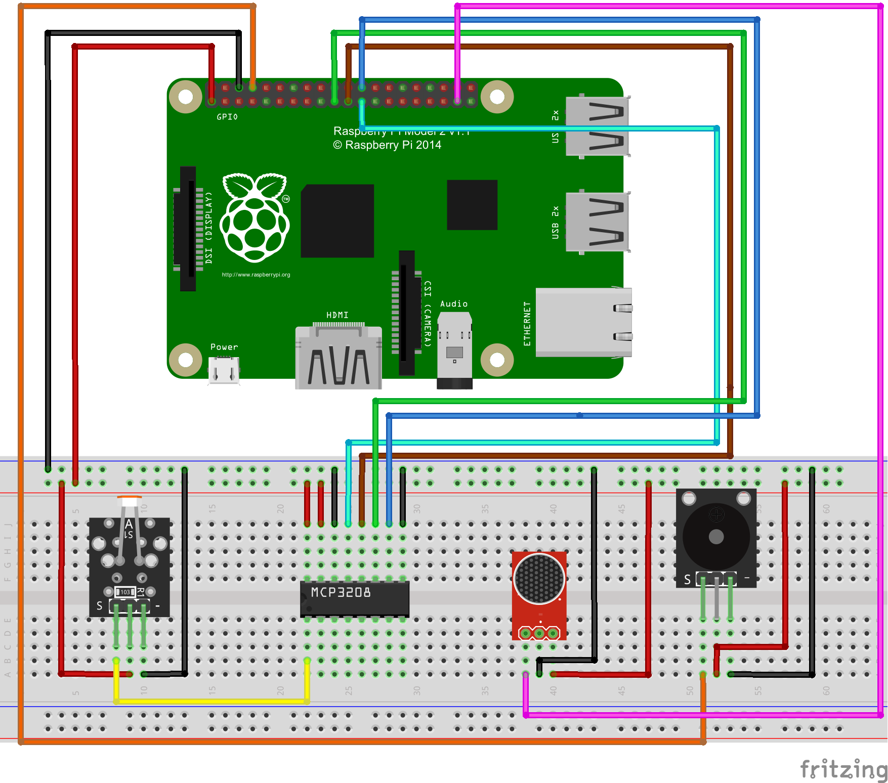
If you don’t know what is GPIO layout, check our tutorial: How to read Raspberry Pi i/o pin diagram (GPIO pin graph)
Note: Please reversing +/- or incorrectly connecting can destroy your raspberry Pi.
Software
You can connect a monitor for your raspberry pi, or remote locate raspberry pi via SSH.
1)enter the following command to create a new file named alarm.py and save this file at direction: /home/pi, and then press enter
sudo nano alarm.py
2)paste the following code in the file “alarm.py”:
import RPi.GPIO as GPIO
import time
import os

buzzer = 14
sound = 26
# change these as desired - they're the pins connected from the
# SPI port on the ADC to the Cobbler
SPICLK = 11
SPIMISO = 9
SPIMOSI = 10
SPICS = 8

def init():
         GPIO.setwarnings(False)
         GPIO.setmode(GPIO.BCM)
         GPIO.setup(buzzer,GPIO.OUT)
         #GPIO.output(buzzer,GPIO.HIGH)
         GPIO.setup(sound,GPIO.IN,pull_up_down=GPIO.PUD_UP)
         # set up the SPI interface pins
         GPIO.setup(SPIMOSI, GPIO.OUT)
         GPIO.setup(SPIMISO, GPIO.IN)
         GPIO.setup(SPICLK, GPIO.OUT)
         GPIO.setup(SPICS, GPIO.OUT)
         pass

#buzzer alarm
def alarm():
         GPIO.output(buzzer,GPIO.LOW)
         time.sleep(1)
         GPIO.output(buzzer,GPIO.HIGH)
         time.sleep(1)


#read SPI data from MCP3008(or MCP3204) chip,8 possible adc's (0 thru 7)
def readadc(adcnum, clockpin, mosipin, misopin, cspin):
        if ((adcnum > 7) or (adcnum < 0)):
                return -1
        GPIO.output(cspin, True)

        GPIO.output(clockpin, False)  # start clock low
        GPIO.output(cspin, False)     # bring CS low

        commandout = adcnum
        commandout |= 0x18  # start bit + single-ended bit
        commandout <<= 3    # we only need to send 5 bits here
        for i in range(5):
                if (commandout & 0x80):
                        GPIO.output(mosipin, True)
                else:
                        GPIO.output(mosipin, False)
                commandout <<= 1
                GPIO.output(clockpin, True)
                GPIO.output(clockpin, False)

        adcout = 0
        # read in one empty bit, one null bit and 10 ADC bits
        for i in range(12):
                GPIO.output(clockpin, True)
                GPIO.output(clockpin, False)
                adcout <<= 1
                if (GPIO.input(misopin)):
                        adcout |= 0x1

        GPIO.output(cspin, True)

        adcout >>= 1       # first bit is 'null' so drop it
        return adcout

# photoresistor connected to adc #0
photo_ch = 0

def main():
         init()
         time.sleep(2)
         print"will detect sonud and light signal"
         while True:
                  photo_value = readadc(photo_ch, SPICLK, SPIMOSI, SPIMISO, SPICS)
                  if (GPIO.input(sound) == False)and (photo_value>=650):  #detected sound signal and light intensity is low
                           print "Alarm!"
                           alarm()
                           time.sleep(1)
                  elif (GPIO.input(sound) == False)and (photo_value<=650):  #detected sound signal,but light intensity is high
                           GPIO.output(buzzer,GPIO.HIGH)
                           print "sound signal is detected ,but light intensity is high!"
                           time.sleep(1)
                  elif (GPIO.input(sound) == True)and (photo_value<=650):
                           GPIO.output(buzzer,GPIO.HIGH)
                           print "sound signal not detected ,light intensity is high!"
                           time.sleep(1)
                  elif (GPIO.input(sound) == True)and (photo_value>=650):
                           GPIO.output(buzzer,GPIO.HIGH)
                           print "sound signal not detected ,light intensity is low!"
                           time.sleep(1)

                  print "light intensity is: " + str("%.1f"%((1024-photo_value)/1024.*100))+"%"


if __name__ =='__main__':
         try:
                  main()
         except KeyboardInterrupt:
                  pass
GPIO.cleanup()
4) after compile the project, press “Ctrl” + “X” to save the code, enter “Y” to confirm saving, and press “enter” to exit the file editor
5) Enter the following command to compile the code(as the last 4 steps), and press “enter” to
complete compiling code:
sudo wget --no-check-certificate http://osoyoo.com/driver/alarm.py
Experiment Result:
enter the following command to run python program
sudo python ./alarm.py
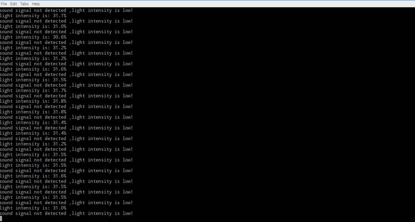
When cover light sensor and make loud sound at the same time, you will hear Intermittent buzzer sound. If uncover the light sensor or stop making loud sound, the buzzer will stop sound. This is the experimental result of sound and light switch.
{:}{:zh}Overview
本文介绍如何用树莓派实现声光控开关设计,声光控开关是通过声音和光照度控制的开关,当环境的亮度达到某个设定值以下,同时环境的噪音超过某个值,这种开关就会开启。在本文中通过树莓派采集声音检测模块和光敏电阻模块输出的声音和光照度信号,通过采集到的声光信号控制开关通断,这里的开关是软件开关(用软件实现),当开关闭合时候,蜂蜜器响起。
Experimental Parts
为了完成设计需要用到一下器件
|
|
Pi3 x1
|
|
|
有源蜂鸣器模块 x1 |
|
|
声音检测模块 x1 |
|
|
光敏电阻模块 x1 |
|
|
面包板 x1 |
|
|
模数转换器 x1 |
|
|
公对公跳线 x若干 |
|
|
公对母跳线 x若干 |
Hardware
Raspberry Pi是一个出色的微型计算机,你可以使用它来控制数字输入和输出。但是当你想用它来处理模拟信号,例如像热敏电阻、电位器等模拟传感器输出时候,Raspberry Pi就有些力不从心了,就需要借助模数转换芯片将模拟信号转换成数字信号。本项目中利用MCP3008把光敏电阻模块输出的电压信号转换成数字信号,Pi根据转换后的数值大小以及声音检测传感器输出的信号控制蜂鸣器鸣叫。MCP3008是一款8通道10位精度的模数转换芯片。
声音检测模块可以检测周围环境的声音强度 , 此传感器只能识别声音的有无 , 能识别声音的大小或者特定频率的声音; 灵敏度可通过模块上的蓝色电位器调节;工作在3.3V-5V,因为树莓派GPIO口一般工作在3.3V电压,所以采用3.3V供电;模块输出数字’0’和数字’1’信号,模 块在环境声音强度达不到设定阈值时, DO 口输出高电平,当外界环境声音强度超过设定阈值时,模块D0输出低电平 ,阈值通过调节电位器设定。器原理图如图所示。
有源蜂鸣器模块采用2TY三极管(8550)驱动,工作在3.3V-5V之间,本文将其接到3.3V电压上,模块低电平触发。
各模块之间与树莓派具体连接请参考下图
在接线的时候请认清模块正负极,不要接反了,否则会烧坏你的Pi和模块。模块的上的GND接Pi上的0V;模块上的VCC接3.3V。对于如何识别Pi的IO口请参考这篇文章: How to read Raspberry Pi i/o pin diagram (GPIO pin graph)
Software
可以把pi直接接到显示器上,也可以通过SSH方式远程登录Pi。
1)编写代码
在/home/pi路径下用nano新建一个alarm.py(名字随意,你喜欢就好!)
sudo nano alarm.py
并往新建的文件中写入如下代码:
import RPi.GPIO as GPIO
import time
import os

buzzer = 14
sound = 26
# change these as desired - they're the pins connected from the
# SPI port on the ADC to the Cobbler
SPICLK = 11
SPIMISO = 9
SPIMOSI = 10
SPICS = 8

def init():
         GPIO.setwarnings(False)
         GPIO.setmode(GPIO.BCM)
         GPIO.setup(buzzer,GPIO.OUT)
         #GPIO.output(buzzer,GPIO.HIGH)
         GPIO.setup(sound,GPIO.IN,pull_up_down=GPIO.PUD_UP)
         # set up the SPI interface pins
         GPIO.setup(SPIMOSI, GPIO.OUT)
         GPIO.setup(SPIMISO, GPIO.IN)
         GPIO.setup(SPICLK, GPIO.OUT)
         GPIO.setup(SPICS, GPIO.OUT)
         pass

#buzzer alarm
def alarm():
         GPIO.output(buzzer,GPIO.LOW)
         time.sleep(1)
         GPIO.output(buzzer,GPIO.HIGH)
         time.sleep(1)


#read SPI data from MCP3008(or MCP3204) chip,8 possible adc's (0 thru 7)
def readadc(adcnum, clockpin, mosipin, misopin, cspin):
        if ((adcnum > 7) or (adcnum < 0)):
                return -1
        GPIO.output(cspin, True)

        GPIO.output(clockpin, False)  # start clock low
        GPIO.output(cspin, False)     # bring CS low

        commandout = adcnum
        commandout |= 0x18  # start bit + single-ended bit
        commandout <<= 3    # we only need to send 5 bits here
        for i in range(5):
                if (commandout & 0x80):
                        GPIO.output(mosipin, True)
                else:
                        GPIO.output(mosipin, False)
                commandout <<= 1
                GPIO.output(clockpin, True)
                GPIO.output(clockpin, False)

        adcout = 0
        # read in one empty bit, one null bit and 10 ADC bits
        for i in range(12):
                GPIO.output(clockpin, True)
                GPIO.output(clockpin, False)
                adcout <<= 1
                if (GPIO.input(misopin)):
                        adcout |= 0x1

        GPIO.output(cspin, True)

        adcout >>= 1       # first bit is 'null' so drop it
        return adcout

# photoresistor connected to adc #0
photo_ch = 0

def main():
         init()
         time.sleep(2)
         print"will detect sonud and light signal"
         while True:
                  photo_value = readadc(photo_ch, SPICLK, SPIMOSI, SPIMISO, SPICS)
                  if (GPIO.input(sound) == False)and (photo_value>=650):  #detected sound signal and light intensity is low
                           print "Alarm!"
                           alarm()
                           time.sleep(1)
                  elif (GPIO.input(sound) == False)and (photo_value<=650):  #detected sound signal,but light intensity is high
                           GPIO.output(buzzer,GPIO.HIGH)
                           print "sound signal is detected ,but light intensity is high!"
                           time.sleep(1)
                  elif (GPIO.input(sound) == True)and (photo_value<=650):
                           GPIO.output(buzzer,GPIO.HIGH)
                           print "sound signal not detected ,light intensity is high!"
                           time.sleep(1)
                  elif (GPIO.input(sound) == True)and (photo_value>=650):
                           GPIO.output(buzzer,GPIO.HIGH)
                           print "sound signal not detected ,light intensity is low!"
                           time.sleep(1)

                  print "light intensity is: " + str("%.1f"%((1024-photo_value)/1024.*100))+"%"


if __name__ =='__main__':
         try:
                  main()
         except KeyboardInterrupt:
                  pass
GPIO.cleanup()
上面的代码可以通过执行下面的shell命令得到
sudo wget --no-check-certificate http://osoyoo.com/driver/alarm.py
2)执行python程序
sudo python ./alarm.py
3)测试
将手遮住光敏电阻模块,同时大声说话(或以其他方式发出响声),会发现间歇性蜂鸣器响起来了;只要将遮住光敏电阻模块的手移开或是停止发出声响,蜂鸣器也随即停止鸣叫。这样就实现了声光控开关的设计。{:}
amber administrator
You must be logged in to post a comment
About the Author