Arduino Tank Car Kit Lesson 2: Install tank car control board
{:en}

Authorized Amazon Seller:
Robot Tank Car Chassis
| Buy from US | Buy from CA | Buy from UK | Buy from DE | Buy from IT | Buy from FR | Buy from ES |
Robot Tank Car Electronic Parts Kit
| Buy from US | Buy from CA | Buy from UK | Buy from DE | Buy from IT | Buy from FR | Buy from ES |
- I. Objective
- III. Parts and Devices
- III. Hardware Installation
- IV. Software Installation:
- V. Testing
Objective:
In this lesson, we will install the most important framework in the tank car and program the car to do some simple movements. If you have passed the test movement in this lesson, it means Arduino UNO board, voltage meter,motor control driver module, motors, batteries,chassis and wire connections between these parts are all functioning well.
As your experiments in future lessons are all based on frame work of Lesson 1 and lesson 2, it is very important to test the installation and sample code in this Lesson properly.
II. Parts and Devices
Package Listing
III. Hardware Installation
I. Adjust the sensitivity of tracking sensor and Install the tracking sensor.
Before assemble the control board, we need to adjust the sensitivity of tracking sensor.
Connect expansion board to tracking sensor as the following graph. Put the expansion board on UNO R3 board and connect Arduino UNO to PC with USB cable.Then adjust the potentiometer on the tracking sensor with cross screwdriver until you get the best sensitivity status: the signal indicate LED light will turn on when sensor is above white ground, and the signal LED will turn off when the sensor is above black track.
II.Install electronic board on tank car chassis
(1)Install Arduino UNO,Expansion board,Driver board,Voltage meter and Buzzer Module on upper acrylic chassis with M3 x 10 philip’s head screws, Install IR receiver with M2.5*8 philip’s head screws.
 Install the ultrasonic sensor on black acrylic board with M1.6*12 philips head screws, then install it on servo arm with philip’s head sharp screws.
(2) Assemble the Neccessary Components
Install bracket (from servo motor package) on mount holder for Ultrasonic Module with 2pcs M1.5*4 Self Tapping Screws.

Install Ultrasonic Module to mount holder with 4pcs M1.4*8 screw and M1.4 nuts

Install the LED lights at the front of tank chassis;
Install the tracking sensor in the lower tank chassis with 2pcs M3x20 copper pillars;
Install the ir infrared obstacle avoidance sensor in the upper tank chassis with 2pcs M3x10 screws and nuts;
Install the battery box on tank car chassis with M3*10 screws.
 |
|
 |
 |
Install the acrylic board on tank car chassis with 4pcs M3x20 copper pillars and 4pcs M3 nuts.
Install the SG90 servo motor at transparent acrylic with 2pcs M2.2*8 self-taping screws.
Install the SG90 servo motor at transparent acrylic with 2pcs M2.2*8 self-taping screws.
Install ESP8266 Expansion Board on UNO R3 board.

Turn the switch of esp8266 to “1” and “2” position, as the following photo shows.

(3)Connection Diagram
Connect Driver board K1 (or K2) and K3 (or K4) sockets to 2 motors as per the following graph.

Connect the 2 LED light to expansion board as per the following graph.

Connect the right and left tracking sensors as the following graph.
![]()
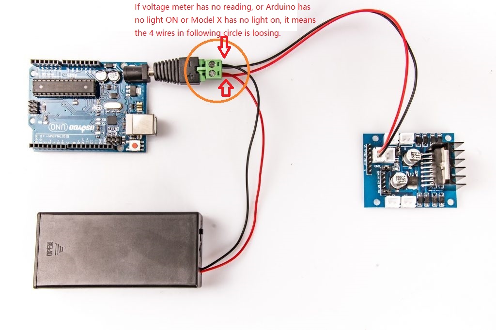
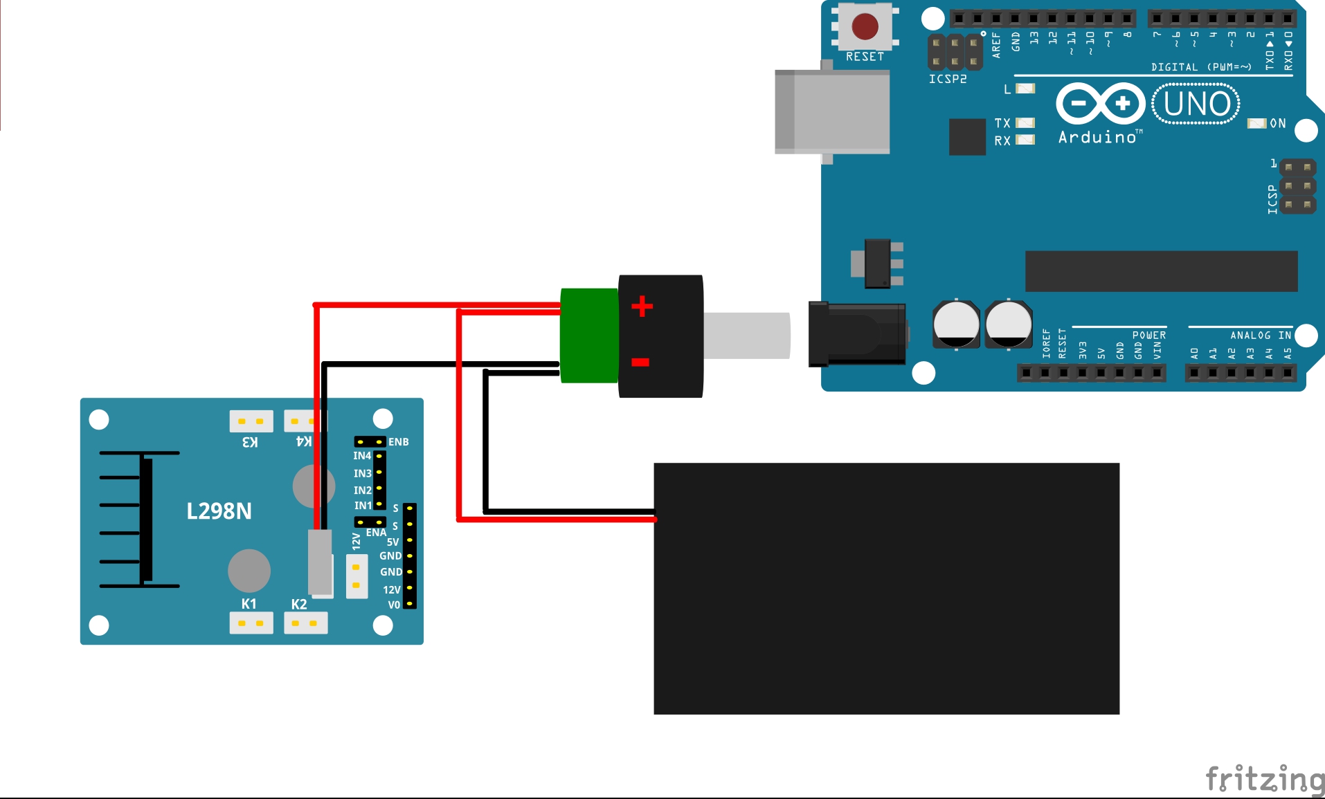
Connect the Uno board, battery box, Voltage Meter and driver board according below connection diagram.

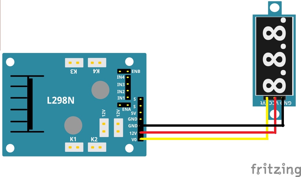
Connect Voltage Meter to driver board as below connection diagram.

Connect buzzer sensor, IR receiver,Ultrasonic Sensor and SG90 servo motor to driver board as below connection diagram.


Connect D5,D6,D8,D9,D10,D12 Pins to driver board 6 control pins as per following graph (these pins are defined in sample code configuration.h file)

Now hardware installation is almost down, you need to put the 18650 batteries inside the holder.Both flat top and button top 18650 battery can be put inside the holder. The button top battery is recommend because it is easier to figure out positive pole of the battery.If you buy flat top battery, you must make sure the positive pole of the battery is put on the + side of the holder.if you make put battery on wrong direction, it will damage the car.Before we install 18650 batteries into the box, we need burn the sample code into Arduino First.
IV. Software Installation:
Step 1: Install latest Arduino IDE (If you have Arduino IDE version after 1.1.16, please skip this step)Download Arduino IDe from https://www.arduino.cc/en/Main/Software?setlang=en , then install the software.
Step2 :The SG90 Servo can rotate approximately 180 degrees. Firstly we make the servo motor go to 90 degree position(middle position), then manually adjust the ultasonic sensor to straight forward direction. Thus to make sure the ultrasonic module can rotate to the left 90 degrees and also can rotate to the right 90 degrees. Find the servo_adjust.zip file in Tutorial/Lesson2/Code or download the servo adjust program from link:
http://www.kookye.com/download/Arduino_Tank_Car_Kit/servo_adjust.zip
Download and unzip, then upload the code to Uno board using Arduino IDE, turn on the power switch on the battery box. the servo motor will go to 90 degree position(middle position), At this time, if the ultrasonic sensor is not facing front direction of the car, you need manually adjust the sensor to straight forward direction.
Youtube link–https://youtu.be/t2kyK2RU0jU
Step 3: Download the libraries from http://www.kookye.com/download/Arduino_Tank_Car_Kit/IRremote.zip open arduino IDE -> click sketch -> Include Libraries->Add .zip Libraries -> choose zip file “IRremote.zip”-> Upload the .zip files
Step 4: Download Lesson One sample code from http://www.kookye.com/download/Arduino_Tank_Car_Kit/tank_robot_lesson2.zip , unzip the download zip file tank_robot_lesson2.zip, you will see a folder called tank_robot_lesson2 .
Step 5: Connect Arduino UNO to PC with USB cable, Open Arduino IDE -> click file -> click Open -> choose code “tank_robot_lesson2.ino” in tank_robot_lesson2 folder, load the code into arduino.
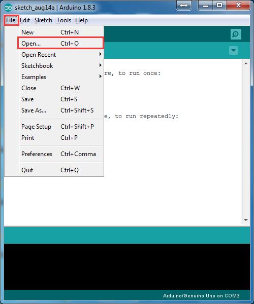
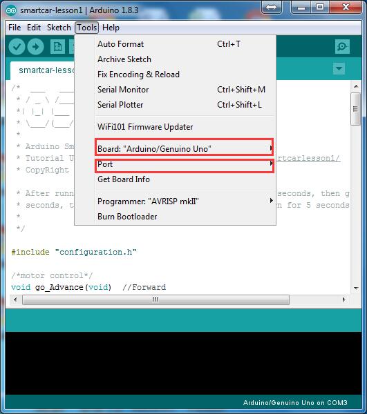
Step 6: Choose corresponding board/port for your project,upload the sketch to the board.
V. Testing :
Connect Arduino from PC, put 2 fully-charged 18650 battery into battery pox(check the box instruction and make sure polar direction is correct). Open the power switch in the box and open arduino IDE, set the buat rate as 9600. You will find the information as follows:
welcome to use kookye tank robot car…
send :line follow/
send :led on/
send :led off/
send :servo/
send :distance/
send :buzzer/
send :go/
send :back/
send : stop/
When you put the car on the ground and send “line follow sensor”, the signal indicate LED light will turn on when sensor is above white ground, and the signal LED will turn off when the sensor is above black track.
When you send “turn on LED”, the LED light on car should turn on. “turn off LED”, the LED light should turn off.
When you send servo, the SG90 servo motor should move.
When you send buzzer, the buzzer should beep.
When you send go ahead, it should go forward;send go back,it should go backward;send stop,it should stop.
If the car does not move as per above mentioned result, you should check your wire connection, battery voltage(must over 7.2v).
![]()
![]()
{:}{:zh}第一部分:硬件安装
坦克智能小车底盘组成图

1.安装电池盒
所需器件
电池盒 x1
一号车板 x1
M3*6十字螺丝 x2
M3螺帽 x2
把电池盒滑盖打开,用M3*6十字螺丝把电池盒靠左侧固定在一号车板活动卡槽里面


2.安装LED
将2个LED灯珠从外侧放到二号车板圆孔中,在内测用塑料螺帽锁紧

3.安装循迹模块
所需器件
M3*12双通铜柱 x2
M3*6十字螺丝 x4
循迹传感器模块 x2
铜柱一端用M3*6十字螺丝固定在4号车板活动卡槽中,另一端将循迹传感器也用M3*6十字螺丝固定在铜柱上


4.安装电机
所需器件
左右侧板 x2
电机 x2
M3*6内六角螺丝 x4(不要用M3*8内六角螺丝,这样可能会顶坏电机转子)
将在侧板上寻找合适孔位,使电机接线端子朝前,电机用M3*6内六角螺丝固定在左右侧板上


5.安装车架
用4颗M3*8内六角螺丝将一号车板和左右侧边偏接起来
用4颗M3*8内六角螺丝将四号车板和左右侧边偏接起来
用2颗M3*8内六角螺丝将二号车板和左右侧边偏接起来


注意:为了使led灯光能够向前照射,二号车板需要竖直安装,与左右侧边之间只需要固定2颗螺丝即可。
用4颗M3*8内六角螺丝将三号车板和左右侧边偏接起来

将M3*6+6铜柱母口一端放在五号车板四角螺丝孔上,再用M3*8内六角螺丝从底盘底部穿过螺丝孔固定到铜柱上。


6.驱动轮安装
驱动轮所用器件
轮片 x4
M3*17双通铜柱 x6
M3*8 内六角螺丝 x12
联轴器 x2
M6*10 x2

将铜柱与轮片用M3*8内六角螺丝固定,两轮片孔位要对其。

将联轴器安图示样子插入驱动轮中,另一侧用M6*10内六角螺丝固定


用黑色小螺丝将联轴器和电机轴固定(再放一张驱动轮装到电机轴上后的照片)

7.安装承重轮
将轴承卡在塑料轮子中,用M6长螺丝穿过螺丝孔中,另一端用M6螺帽固定在侧板上,使用M6内六角扳手和M6扳手将螺丝拧紧。


8.安装履带
履带长度可以随意拼接,本款坦克小车约需要70节履带即可,安装履带时候需要注意驱动轮和承重轮对其,如果没有对齐,可以调节驱动轮使其对齐(这里最好加一个拆装履带的动态图和调节动态图)
9.安装舵机
用两颗M2.5*8十字螺丝和螺帽将舵机固定在金属面板上。

10.安装亚克力
将所有控制电路板和一些传感器按照图示样子安装在亚克力面板上,亚克力面板兼容arduino UNO、Mega 2560、raspberry Pi三块常用开源主板螺丝孔位。用M3*10十字螺丝和螺帽将arduino uno,L298N,电压表,蜂鸣器亚克力面板上,用M2.5*8十字螺丝和螺帽将红外接收器按照图示样子安装在亚克力上。(注意:最好用PS做一张图,标明那些孔位是UNO的,那些是2560的,那些是树莓派的。)

第二部分:接线
1.电机
取出6pin电机线,带6pin端子一端插在电机上,把其中带2pin接线端子穿过金属面板和亚克力面板,剩余4pin是编码器电源线和信号线,暂时不使用,在后面的课程中会使用到,先将它们用尼龙扎带绑在电机上。将左边电机红黑线接到L298N的K1或K2接口;右边电机接到K3或K4接口。
2.esp8266 uart wifi shield
将esp8266 uart wifi shield插到arduino uno板上,esp8266 uart wifi shield引出了UNO的所有GPIO口,可以作为UNO的扩展板使用,同时,esp8266 uart wifi shield还具有wifi功能,支持AP/STA模式,默认工作在AP模式。esp8266 uart wifi shield与arduino之间通过串口进行通讯,默认波特率为9600,也就是说esp8266 uart wifi shield也就是一个串口wifi模块。关于esp8266 uart wifi shield的详细介绍请看下面链接。
http://osoyoo.com/2016/09/18/esp8266-uart-wifi-shield-use-guide/

3.L298N
L298N是电机驱动器,能接4路直流电机,板上引出了5V输出口和12V输出口,在我们的坦克小车中,5V用于给舵机供电。
| L298N | esp8266 uart wifi shield |
| IN1 | D8 |
| IN2 | D9 |
| IN3 | D10 |
| IN4 | D12 |
| ENA | D5 |
| ENB | D6 |
4.电压表
| L298N | 电压表 |
| GND | GND |
| VCC | 12V |
| Vd | V0 |
5.电源
坦克小车通过2节18650电池供电,将18650电池放到电池盒中(注意方向),将电池盒,uno,L298N按照图示接线。
6.循迹
| esp8266 uart wifi shield | 左循迹 |
| 5V | VCC |
| GND | GND |
| A0 | DO |
| esp8266 uart wifi shield | 右循迹 |
| 5V | VCC |
| GND | GND |
| A1 | DO |
7.蜂鸣器
| esp8266 uart wifi shield | 蜂鸣器 |
| 5V | VCC |
| GND | GND |
| D7 | IO |
8.红外接收器
| ESP8266 UNO SHIELD | 红外接收器 |
| 5V | VCC |
| GND | GND |
| D13 | S |
9.LED
10.舵机
舵机有三条线,分别为VCC、GND、S,电机再转动瞬间会把电压拉的比较低,为了不影响arduino uno正常工作,将舵机电源L298N上的5V输出供电,同时将控制信号引到L298N上
| 舵机 | L298N | esp8266 uart wifi shield |
| GND | GND | |
| VCC | 5V | |
| S | S | D11 |
esp8266 uart wifi shield与uno之间通过UART连接通讯,将esp8266 uart wifi shield上两位拨码开关拨到”12″位置,使esp8266 uart wifi shield与uno断开连接,向arduino uno中烧录一个程序使舵机转到90度位置。
11.超声波
取出舵机配套的一字叶片,按照图示样子套在舵机旋转轴上

然后将L型超声波支架用M2自攻螺丝固定在叶片上。超声波模块有4pin,分别是VCC、Trig、Echo、GND,按照下表接线
| esp8266 uart wifi shield | 超声波模块 |
| 5V | VCC |
| GND | GND |
| A2 | Trig |
| A3 | Echo |
12.测试
下载http://osoyoo.com/driver/tank_robot_lesson1.zip,解压文件并烧录到arduino中,在进行测试之前,先调节一下循迹传感器的灵敏度。在白色地板上贴一条10mm左右的黑色电工胶,把坦克小车上的2个循迹传感器放在黑色电工胶上,用十字螺丝刀调节可调电位器,使循迹模块信号指示灯刚好熄灭,再将循迹传感器离开黑色区域,使信号指示灯刚好亮起,这表示循迹传感器灵敏度调节好了。
用usb线将坦克小车和pc连接起来,打开电池盒开关打开arduino IDE的Serial Monitor将波特率设置为9600,Serial Monitor会向终端打印出如下信息:
welcome to use osoyoo tank robot car…
send :test line follow sensor
send :turn on LED
send :turn off LED
send : test servo
send : test HC-SR04
send : test buzzer
send : test robot go ahead
send : test robot go back
send : test robot stop
—————————————————>>
串口发送”line follow”会测试循迹传感器,终端将会打印出是2个循迹传感器是否在黑线上;
串口发送”led on”会打开LED;
串口发送”led off”会关闭LED;
串口发送”servo”会使servo旋转,舵机会从0度转到180度,再从180度转到0度,最后回到90度;
串口发送”hc-sr04″会获取到超声波与障碍物之间的距离;
串口发送”buzzer”会使蜂鸣器响一下;
串口发送”go”会使坦克小车前进;
串口发送”back”会使坦克小车后退;
串口发送”stop”会使坦克小车停止;
用遥控器对着红外接收器按遥控器上按键,终端会打印出每个按键的红外编码。
至于详细原理在后面的课程中会详细讲解。{:}
amber administrator
You must be logged in to post a comment
About the Author